Home »


Short specification
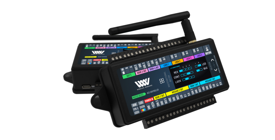
| Product Description | The Wireless-Wiegand is a wireless access control bridge that transmits wireless signals (Two Wiegand interface; Four inputs for Exit buttons; Four inputs for Door Position sensors; Four relays) between remote Door hardware and a central access control module or panel. |
| Operating Voltage | 12–24 VDC |
| Operating Current | 0.2A @12 VDC, 0.1A @ 24 VDC current |
| Protocol | Wiegand (26–56 bit) |
| Relays | Four (4) dry form “C” 1.5A rated relay |
| Inputs | Eight (8) inputs (dry contact) from 0 to 5 VDC One (1) input (dry contact) 0 to 5 VDC for local emergency relay opening |
Before you start
Ensure you have all required materials and recommended tools needed for a successful installation.
| Part / Tool | Description | Quantity |
|---|---|---|
| WWS+WWM | These units function as a working pair. Installation and configuration can not be completed unless both units are available. | x2 |
| Antenna | Provided | x2 one per unit |
| ⅛ inch crosshead screwdriver | Not included, but recommended. | x1 |
| Power Supply | 12-24 VDC, 2A | x2 one per unit |
Structure diagram
Overview
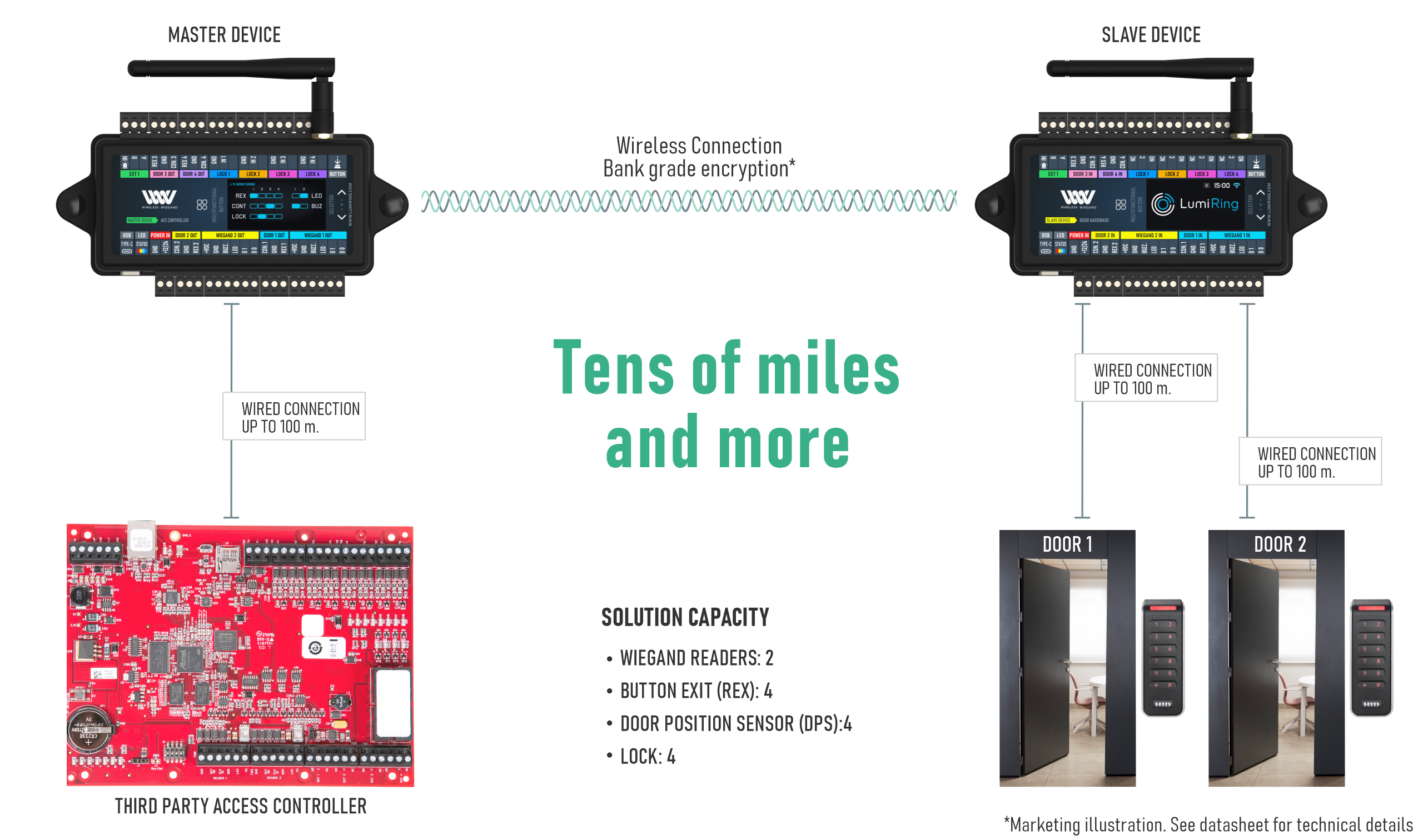
Wireless Wiegand replaces the cable between door-side access devices and the main control panel. It transmits low-voltage signals such as card reads, lock commands, and door status wirelessly and securely.
The system supports standard (non-proprietary) Wiegand and OSDP, RS-485, and relay signals, using an encrypted, interference-resistant wireless transport protocol to replace traditional cabling. Communication is encrypted, interference-resistant, and built on a purposely developed protocol that delivers greater security and flexibility than traditional cabling.
When wiring is slow, costly, or impractical, Wireless Wiegand makes deployment possible in historic sites, elevators, parking lots, construction zones, and anywhere cabling isn’t an option.

Quick Start
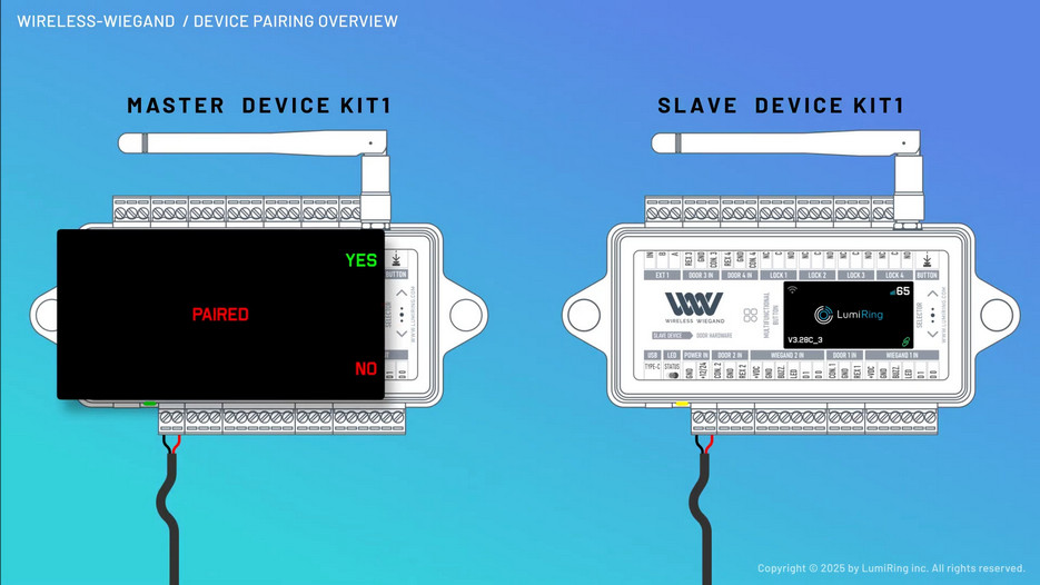
Configure and pair units
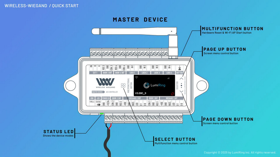
- Screw on the included antenna, ensuring that it’s tight enough that it doesn’t fall or swing freely in any position. Complete this process on both units.
- Before mounting, connect both units to temporary power.
- Wait for device booting and connected.
- Check the display information on both devices:
- Pair icon must be green.
- Signal Level must be more than 40 units.
- Led color must be green or yellow.
- Disconnect from temporary power.
Understanding LED indication
| LED color/behavior | Device status | Description |
|---|---|---|
| Blue (flashing) | Waiting for pairing. | The device is in its default state, waiting to be paired with another device. |
| Red/Green (flashing) | No radio signal | The device is unable to detect any radio signal. |
| Green (solid) | There's a radio signal. Excellent quality. |
The device has a strong and stable radio signal connection. |
| Yellow (solid) | There's a radio signal. Normal quality. |
The device has a radio signal of adequate quality. |
| Red (solid) | There is a radio signal. Poor quality. |
The device has a weak radio signal with poor quality. |
| White (solid) | Wi-Fi AP enabled | The device's Wi-Fi Access Point (AP) is activated. |
Mount and wire units
- Install each unit in a high, dry, unobstructed location.
⚠ The devices is NOT water resistant. - Connect 12-24 VDC power to the red terminal block on each unit.
- Verify STATUS LED on both units green or yellow (depend on signal quality).
Verify the PAIRING ICON on both devices – must be green.
Verify the SIGNAL LEVEL icon – must showing more than 20 units.
This confirms successful pairing. - Wire units based on their classification.
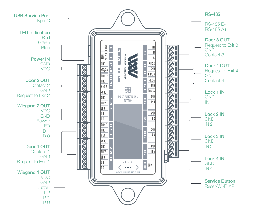
Master device: connect access panel to corresponding terminal blocks.
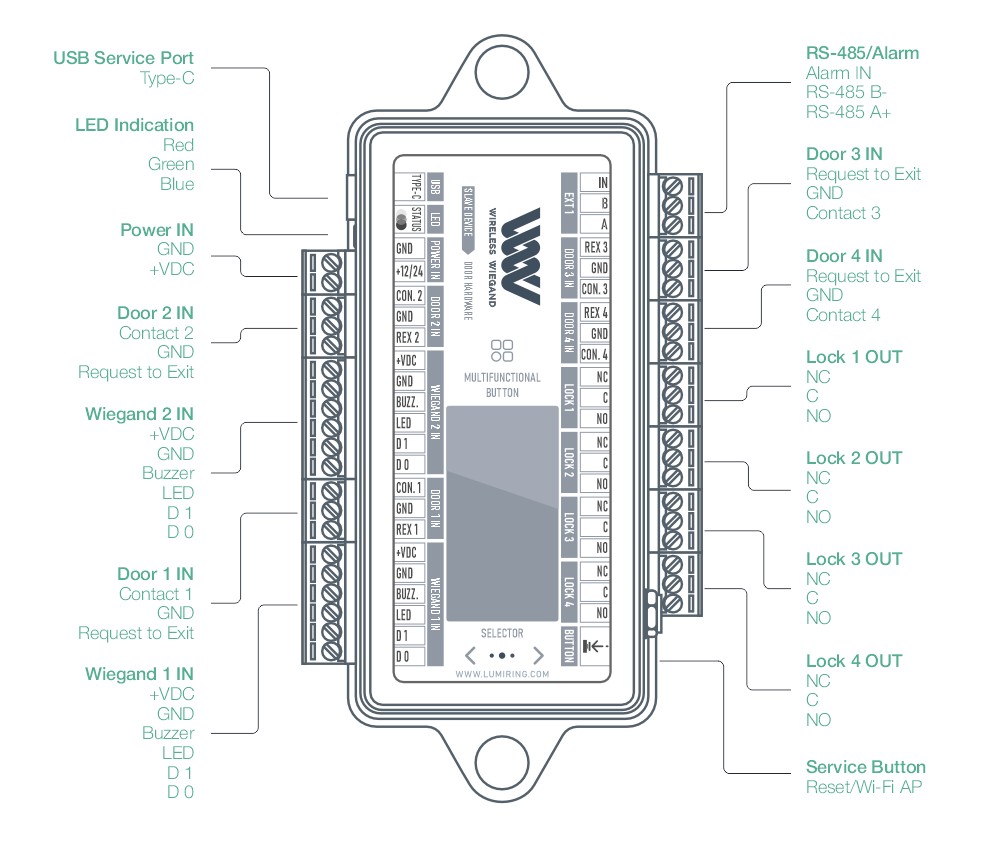
Slave device: connect door hardware to corresponding terminal blocks.
Mounting
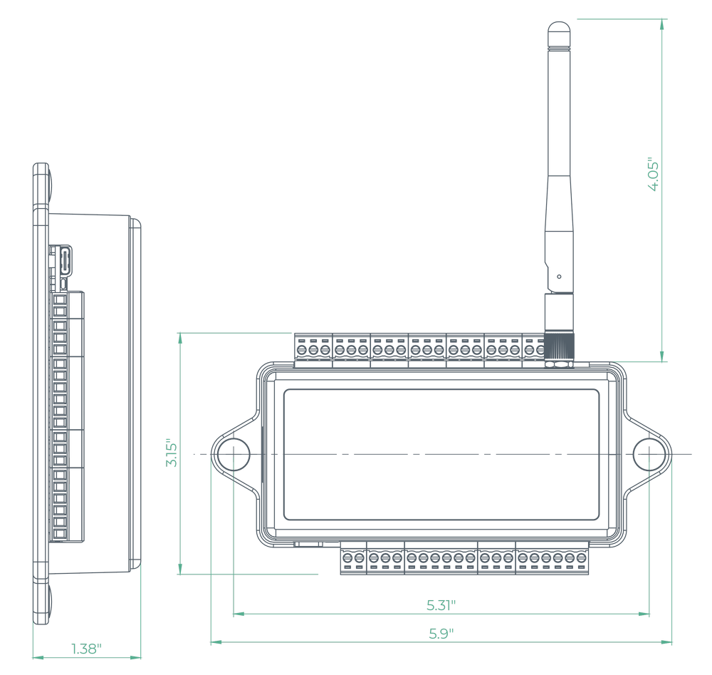
Attach the included antenna securely, making sure it’s tightened enough to stay firmly in place without wobbling or shifting. Install the unit in a location where the antenna has a mostly clear line of sight to its paired unit—ideally mounted high and near an exterior wall or window if placed indoors. Power and a Wiegand connection will be required for operation.
The Wireless-Wiegand is NOT water resistant.
Wiring
Terminal block description
Slave device wiring
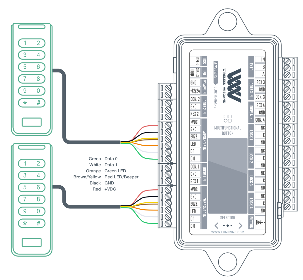
Device supports different kind of Wiegand readers. For a complete list of tested devices, please refer to the user manual on page 33.
NOTE:
- Before you start building cable networks for Wiegand readers, read the interface specifications.
- The wiring diagram is shown as an example. In reality, wire colors may vary depending on the model of the third-party reader.
- Please refer to the reader manufacturer’s instructions.
ATTENTION:
The Readers power is pass-through. If the device is powered with 24V, the readers will receive the same power.
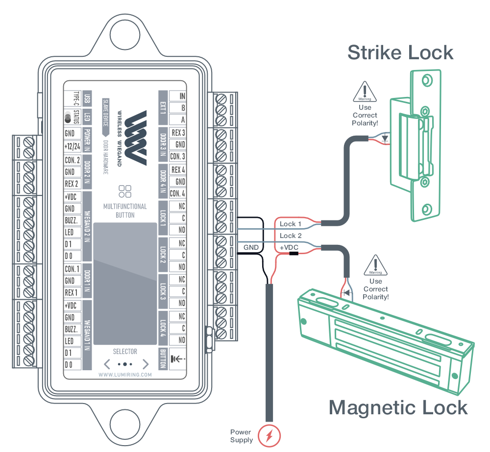
The device supports connection of any executive equipment used in access control systems. First of all, these are various locks.
NOTE:
- Specify the “Impulse” control type in the controller settings when a strike lock is connected.
- Specify the “Trigger” control type in the controller settings when a magnetic lock is connected.
WARNING:
A protective diode is used to protect the device from reverse currents when an electromagnetic or electromechanical lock is triggered. The protective diode is is connected in parallel with the contacts of the lock. THE DIODE IS CONNECTED IN REVERSE POLARITY. The diode must be installed directly on the contacts of the lock. Suitable diodes include SR5100, SF18, SF56, HER307, and similar. Instead of diodes, varistors 5D330K, 7D330K, 10D470K, and 10D390K can be used, for which there is no need to observe polarity.
NOTE:
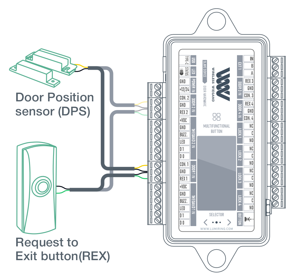
- Specify the “Open” condition in the Сontroller settings when a door sensor is connected.
- Connecting to the “DOOR 3” and “DOOR 4” connector is done in the same way.
- Specify the “Closed” condition in the Сontroller settings when an exit button is connected.
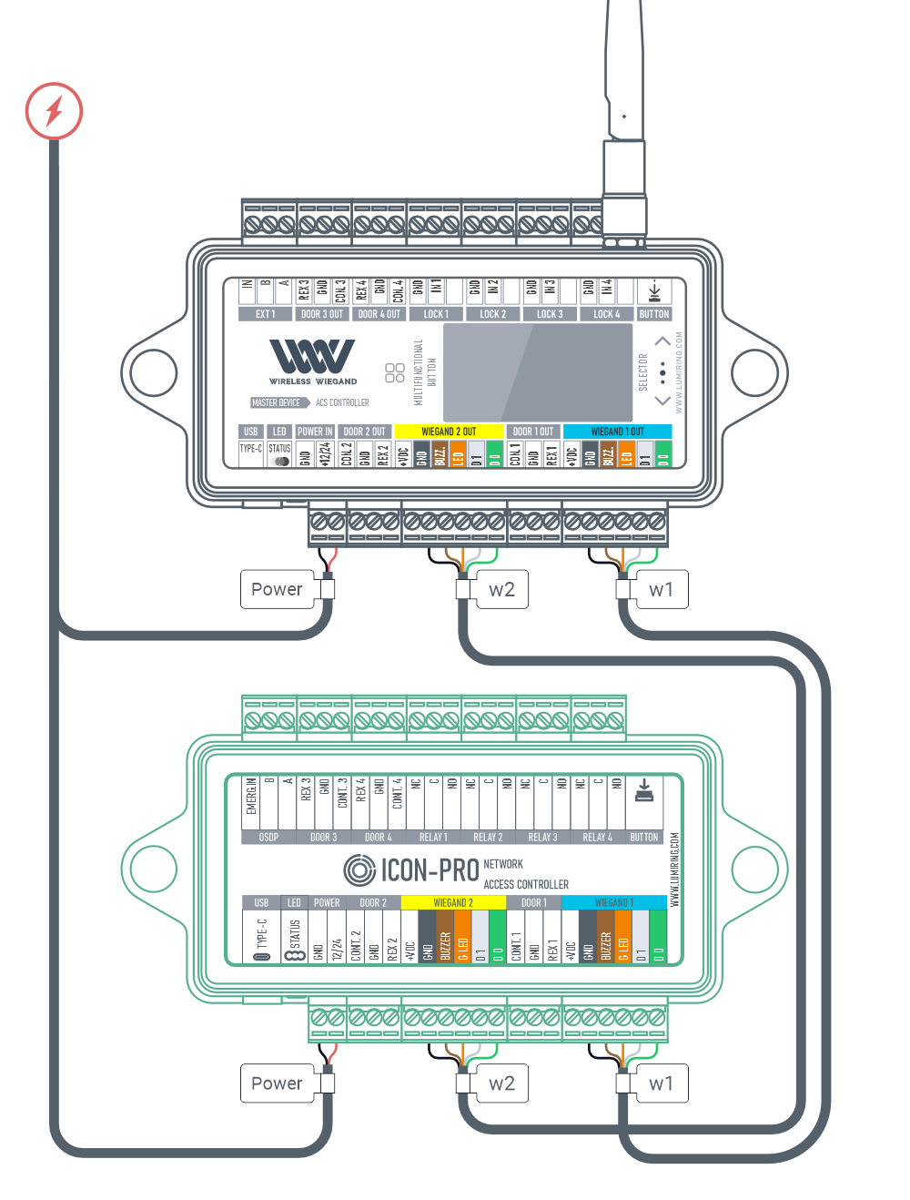
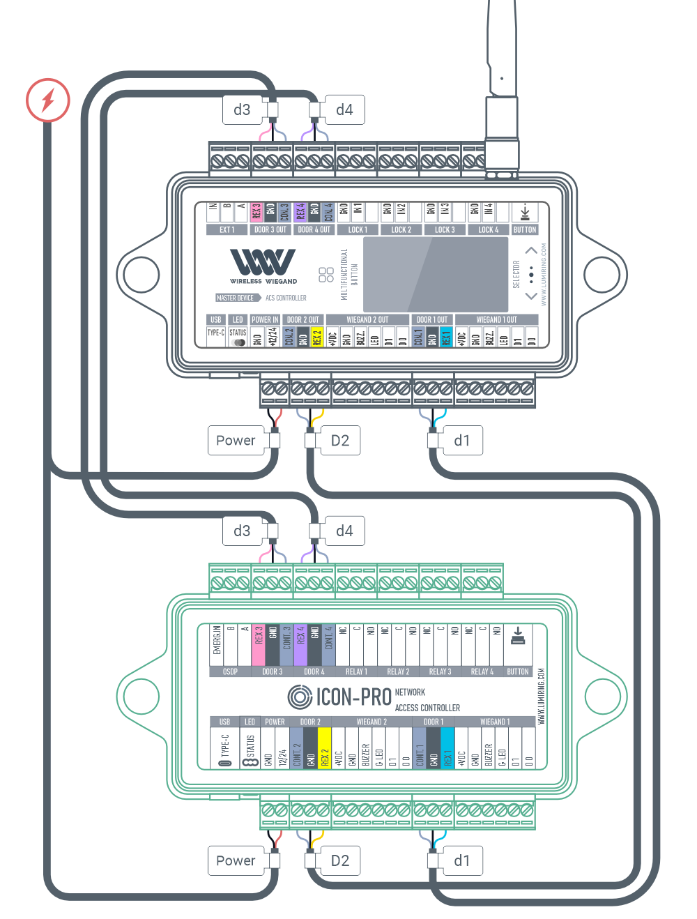
Master device wiring

Device screen menu
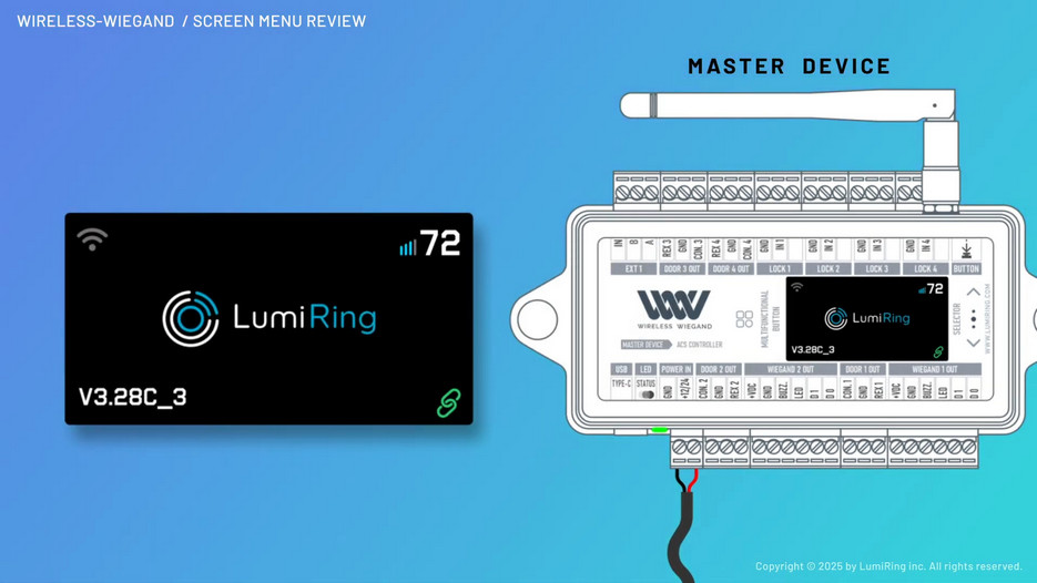
Using the on-screen menu allows for quick and efficient system checks and diagnostics.
You don’t need any additional tools to monitor connection quality, packet loss, or signal performance. All the necessary data is available both in real-time (online mode) and as detailed 24-hour graphs, providing a clear overview of system performance over a selected period.
Key Features:
- Device Information: View model, firmware, and configuration details.
- Event Loss Statistics: Analyze event loss for reliable system performance.
- Packet Loss Graph: Monitor packet loss trends in real-time or over 24 hours.
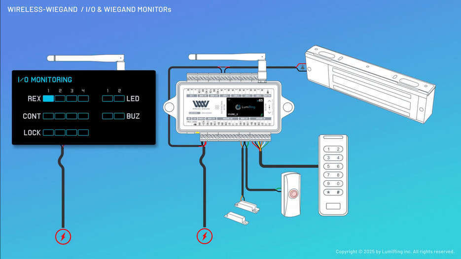
- Input and Output Monitor: Track input/output signals for seamless diagnostics.
- Wiegand Monitor: Display transmitted Wiegand codes for accuracy and debugging.
Pairing
I/O & Wiegand monitor overview
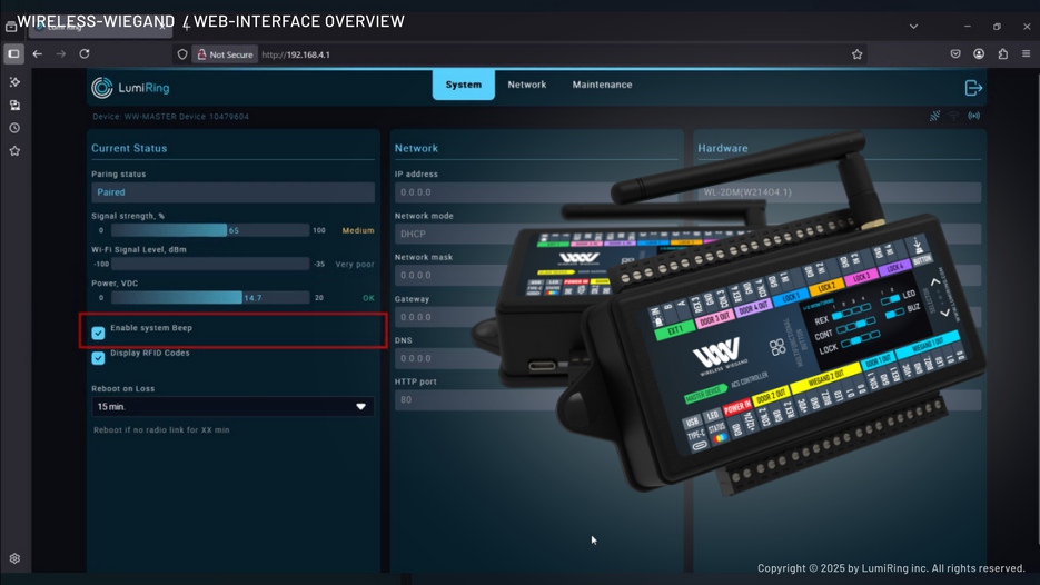
Web-interface
The built-in web interface in Wireless-Wiegand devices makes management, configuration, and diagnostics significantly easier. It provides users with convenient access to all key system functions through any browser, without the need for additional software installation.
- Firmware Updates: Easily update the firmware to access new features and improvements.
- Fine-Tuning Wiegand Operation Modes: Customize Wiegand protocol parameters to suit your hardware.
- Factory Reset: Restore the device to its default settings when needed.
- Monitoring and Diagnostics: View real-time packet loss graphs, event statistics, and connection quality.
- Device Information Access: Retrieve data about the current state of the device, including model, firmware version, and network settings.
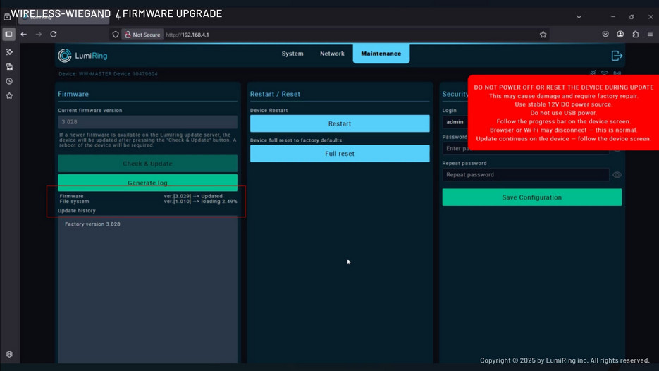
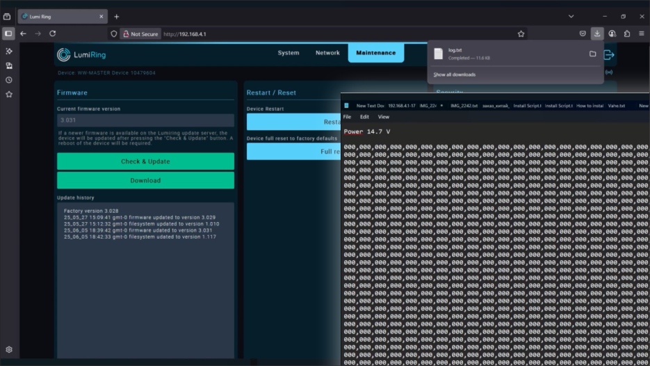
Firmware update
Update procedure
• To download a new firmware version, connect to a network with Internet access in the Network section.
• Click the “Check & Update” button and wait until the update process completes.
• A modal window will prompt you to reboot the device.
• After restarting, verify that the device version has changed.
NOTE:
- It is recommended to upgrade the device to the latest firmware version before use.
- The device must be connected to the Internet and close to a Wi-Fi router during the update.
- The update duration depends on the Internet connection quality and firmware version but usually takes a maximum of 5 minutes. If the update takes more than 5 minutes, forcibly reboot the device by switching off the power and trying the update again.
- A power failure or network connection interruption during the update may cause a firmware update application error. If this happens, disconnect power from the device for 10 seconds and reconnect. Leave the unit switched on for 5 minutes without attempting to connect or log into the web interface. The unit will automatically download the latest previously used firmware version and resume operation.
Logs
The update log file is essential for diagnosing and resolving issues related to device firmware updates.
If you are experiencing difficulties updating your device, we highly recommend providing this log file to our technical support team. Doing so will help us quickly identify the root cause of the problem and offer an effective solution.
FAQ
General Wireless-Wiegand
Wireless Wiegand uses AES 128-bit encryption and a custom radio protocol to protect against spoofing, jamming, and interception. It features connection supervision, keepalives, event logging, and live signal charts — giving you full visibility and control at all times. It’s secure by design, not just by encryption.
Wireless Wiegand works across miles — and more. In real-world conditions, range extends tens of miles, and with clear line-of-sight, it’s virtually unlimited. For even greater distance, use directional antennas and elevated mounting to maximize performance.
Contact us

Still have questions?